Profound and Detailed
Introduction to HART Protocol Burst Mode
2024-01-24
1. Review of key points of HART protocol
 The HART protocol is one of many fieldbuses suitable for process industries. The physical layer includes RS-485, FSK (Frequency Shift Keying), PSK (Phase Shift Keying), IEEE 802.15.4 (Industrial Wireless), IEEE 802.3 (Ethernet network), IR (infrared). Among them, the FSK physical layer compatible with 4~20mA is the most widely used. The master station is based on the physical layer of RS-485, FSK, PSK and IR, and implements the link layer of the simple token mechanism. There is a responsive link layer between the master station and the slave station. Based on the IEEE 802.15.4 physical layer, WirelessHART implements a TDMA (Time Division Multiple Access) link layer. HART IP based on the IEEE 802.3 physical layer performs the carrier sense/collision avoidance link layer of Ethernet.
The HART protocol application layer transmits data and status information based on common commands that must be supported, optional common commands, and customized special commands. Currently, equipment manufacturers are required to provide field device integration (FDI) file packages based on electronic device description files for the integration application of HART main control systems or other main control devices. Equipment DTM is optionally provided by equipment manufacturers. It is a must-provide equipment type manager in individual main control systems and is used for integrated application, advanced diagnosis, and asset management of equipment.
 HART protocol data communication uses master station request and slave station reply as the main methods. In order to improve transmission efficiency, save the master station request link, reduce node power consumption, etc., for fixed format data and status information, the slave station actively initiates and transmits data and status information. The way of data and status information is Burst mode.
2. Burst Working Mode
 In order to support the regular transmission of data and diagnostic information from field devices to master control devices, the data link layer of the HART protocol defines an operating mode. In this mode of operation, field devices can periodically broadcast information onto the communications link. When a field device broadcasts data and diagnostic information in a synchronous loop without requiring continuous polling by the master device, it is said to be in burst mode. On the wired HART communication link, no matter how many field devices there are, only one field device is allowed to be in burst mode. WirelessHART field devices are all in burst working mode, but in the same time slot and the same channel at the time division multiple access (TDMA) communication link layer, only one field device is in the transmitting state.
The English description of the burst mode device is "Burst-Mode Device". This is a digital response device that regularly provides process data and diagnostic information. It is an independent broadcast device, and its working mode is configured by the master station device.
3. Configuration Content of Burst Working Mode
The Burst working mode supports the use of "burst" messages to periodically publish process data. In this mode, field devices are instructed to continuously publish process data and status information without requiring any further action from the master station. The master station configures the working mode of the field device through the following commands.
l Command 103 write burst period;
l Command 104 writes burst trigger mode;
l Command 105 reads burst mode configuration;
l Command 107 writes burst device variables;
l Command 108 writes the burst mode command number;
l Command 109 burst mode control;
In addition, there are two commands specifically designed for I/O systems and WirelessHART adapters:
l Command 101 reads the subdevice to burst messages;
l Command 102 maps child devices to burst messages.
In addition, devices implementing burst mode must configure at least 3 burst messages. Each burst must allow for different configurations. Each burst message can be a different command, trigger condition, update period, device variable set, etc.
3.1 Configure Burst Cycle:
The master station configures the burst cycle of the device through common command No. 103, and configures the shortest burst cycle and the longest burst cycle. Among them, the limit value of the shortest burst period has different requirements in different physical layers, see the table below.
Minimum Update Rates Allowed by Physical Layer(in Seconds)
Physical Layer | Minimum Value | Default Period |
FSK | 0.500 | N/A |
PSK | 0.100 | N/A |
RS-485 | 0.100 | N/A |
IEEE STD 802.15.4-2006 | 0.100 | 60 |
HART-IP | 0.050 | 1.0 |
The longest burst period must not exceed 3600 seconds, and can be selected from the options in the table below that are no shorter than the shortest burst period.
Update Periods Allowed(in Seconds)
<0.001 Not Allowed | 0.020 | 1.000 | 32.000 |
0.001 | 0.050 | 2.000 | 60~3600(Any Value) |
0.002 | 0.100 | 4.000 | ˃ 3600 Not Allowed |
0.005 | 0.250 | 8.000 | - |
0.010 | 0.500 | 16.000 | - |
As long as the trigger conditions in command 104 are met, the device must publish Burst information in the shortest burst period. When the trigger conditions configured in command 104 are not met, the field device must publish Burst information with the longest burst period.
3.2 Configure Burst Trigger Mode:
The master station configures the Burst trigger mode of the device through common command 104. The trigger modes are divided into the following five types:
l Continuous trigger mode (Continuous): Continuous burst messages are released continuously with the shortest burst period.
l Window trigger mode (Window): When the source value deviates from and exceeds the specified window value, messages are sent with the shortest burst period.
l Rising trigger mode (Rising): When the source value rises above the specified trigger value, messages are sent with the shortest burst period.
l Falling trigger mode (Falling): When the source value is lower than the specified trigger value, messages are sent with the shortest burst period.
l Change trigger mode (On-Change): When any value in the message changes, the message is sent with the shortest burst period.
For I/O systems, when a burst message originates from a subdevice, if the engineering unit in the subdevice changes, the burst message must be published with the shortest burst period specified in command 103.
3.2.1. Window Trigger Mode
The window is a symmetrical window around the last sent value. When the deviation of the source value is not greater than the window, the next Burst information is sent with the "maximum update period". When the source value deviates from and exceeds the specified window, the next Burst information is sent with the shortest burst period. The image below demonstrates window mode.

3.2.2. Rising Trigger Mode
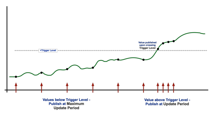
When the source value does not exceed the specified trigger value (Trigger Level), the next Burst information is sent with the "maximum update period". Once the Trigger Level is exceeded, the update time will change. As long as the source value remains above the trigger level, burst messages will be published at the rate indicated by the update period. If the value is lower than the trigger value, the update time will drop to the maximum update period.
3.2.3. Falling Trigger Mode
A burst message is triggered when the source value is lower than the specified trigger value. Burst messages will be published at the rate indicated by the update period, otherwise the update time will drop to the maximum update period.
3.2.4. On-Change Trigger Mode
A burst message is triggered when any value in the burst message changes. The burst message will be published at the rate indicated by the update period, otherwise the update time will drop to the maximum update period.
3.3 Configure Burst Device Variables:
The master station configures the Burst device variables of the device through common command No. 107. Device variables are used in burst command 9 or command 33 to complete data upload. The host always sends 9 data bytes in the request to set device variable values. Unused slots will be set to 250 - "unused". Command 33 only accepts up to 4 slots (i.e. slots 0-3), the others should be set by the host to 250 - "unused". In either case, the field device will ignore the settings in slots 4-7 when issuing command 33.
The last byte indicates which burst message the command applies to.
3.4 Configure Burst Device Command Number:
The master station configures the Burst command number of the device through common command No. 108, that is, selects the device to send the response message of the command number in burst mode. Commands 1, 2, 3, 9, 38 and 48 shall be supported in all burst mode devices, if command 33 is implemented in the field device it must be added to the command number in burst mode.
If the trigger mode is not "continuous" and the device variable classification of the trigger source does not match the new command number, the new command number will be accepted and the response code "Warning - Burst trigger mode has automatically changed to continuous trigger". The device must correct the classification, unit code, reset to "continuous" (trigger mode 0), and issue continuously on the update cycle until another 104 command is received.
3.5 Configuring Burst Mode
The master station configures the Burst mode of the device through common command No. 109. Commands are used to enter and exit burst mode on the device's token passing or TDMA data link layer. The response data bytes issued should conform to the bytes specified using Command 108 Write Burst Mode Command Number and Command 107 Write Burst Device Variable.
Response codes for the delayed response mechanism can only be used when publishing on the TDMA data link is enabled. If the device is unable to obtain any bandwidth to handle the newly enabled burst messages, it must return "No Bandwidth Available" or if the device is able to obtain less bandwidth than requested, it must return "Update Period Increased". When burst mode is turned off, delayed responses are not allowed.
When a burst message number is not included, the device must assume that burst message 0 is being activated or deactivated for publication on the token passing data link. (When a single request byte is received, only burst mode control codes 0 and 1 are valid).
l The disabled Burst function has only one mode, namely (Off) shutdown mode; (control code 0)
l There are four modes for enabling the Burst function.
1) When the physical layer is only FSK, PSK or RS-485, select (Enable Burst on Token-Passing Data Link Layer only) (control code 1)
2) The physical layer is only selected for IEEE STD 802.15.4-2006 (that is, supports WirelessHART communication protocol) (Enable Burst on TDMA Data-Link Layer only) (control code 2)
3) When both the above 1 and 2 modes are available, select (Enable Burst on TDMA and Token Passing Data Link Layers) (control code 3)
4) When HART-IP is supported, select (Enable Burst on HART-IP connection) (control code 4)
4.Burst Mode Device State Machine:
Glossary:
l BACK (Burst Acknowledge): A slave device response sent to the master device without a corresponding master device request (ie, no STX).
l BT (Burst Timer): used by burst mode devices to trigger the transmission of BACK. When BT expires (i.e. reaches 0), BACK is sent.
l RT1 (Link Quiet Time): It is found that there is ongoing communication on the link and the delay time for backing off.
l RT2 (Link Grant Time): When it is uncertain whether there is communication on the link, this time length needs to be set to detect potential communication. If no communication is detected within this time, prepare to start transmitting data.
l STO (Slave Time-Out): Slave time-out, which is the maximum time allowed after the slave device starts transmitting.
4.1 Introduction to Receiving State Machine Logic:

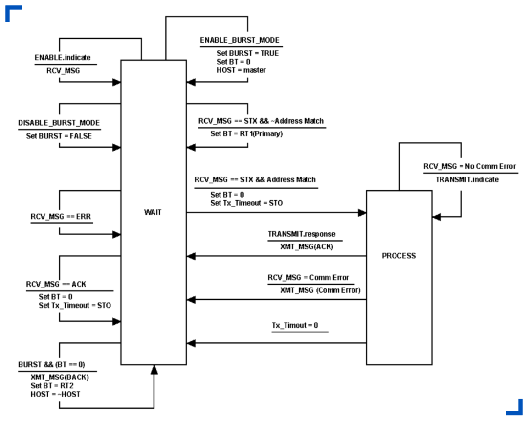
When the burst mode device state machine is in the waiting state, if it receives an instruction from the master device to enable the burst mode, the BT value can be set to 0. That is, prepare to send BACK immediately.
When the Burst mode device state machine is in the waiting state, it receives a request from the master device to other slave devices. It needs to set the BT value to the same RT1 value as the master device. On different physical layers, this time setting The values are different. When the physical layer is FSK, it is 33 character times. When the physical layer is RS-485, it is 33 character time when 1200bps, and when it is greater than 1200bps, it is 32ms+6 character time. When the physical layer is PSK, it is 42ms. When on the infrared physical layer, it is 261ms.
When the burst mode device state machine is in the waiting state and receives a request from the master device, it needs to set the BT time to 0 and set the response timeout time STO. On different physical layers, the STO value is set for different lengths of time. When the physical layer is FSK, it is 28 character times. When the physical layer is RS-485, it is 28 character times at 1200bps, and 32ms when it is greater than 1200bps. When the physical layer is PSK, it is 32ms. When on the infrared physical layer, it is 30ms. The state machine switches to the process processing state, parses the request and prepares a response. After replying with a correct response, or communication error or reply response timeout, it will return to the waiting state.
When the burst (Burst) t mode device state machine is in the waiting state, when the received data type is ACK, the BT value is set to 0, and the transmission timeout (STO) needs to be set.
When the burst mode device state machine is in the waiting state, when the BT value arrives, the BT value time needs to be set to RT2 and BACK is sent alternately to the first master device and the second master device. On different physical layers, the STO value is set for different lengths of time. When the physical layer is FSK, it is 8 character times. When the physical layer is RS-485, it is 8 character time when 1200bps, and when it is greater than 1200bps, it is 3ms+6 character time. When the physical layer is PSK, it is 14ms. When on the infrared physical layer, it is 7ms. In other cases, it remains in a waiting state.
<< Previous page
Next page >>