Profound and Detailed
NE 89 Temperature Transmitter with Digital Signal Processing (Part 1)
2024-03-15
 Temperature transmitters with digital signal processing have been used in a variety of industrial applications. The analog signals of thermal resistors or thermocouples are processed by them and provided to higher-level controllers. The controller applies the processed signals to the monitoring, control and optimization of industrial processes. NAMUR has developed this recommendation based on national and international standards and experience in specific applications. This recommendation describes the requirements for electronic temperature transmitters with digital signal processing.
1. Introduction to Digital Temperature Transmitter
In a digital temperature transmitter, the analog signal from the sensor is converted into a digital signal by an analog/digital converter (ADC) and then processed in a microcontroller. On the output side, a microcontroller controls a digital/analog converter (DAC) to convert the digital signal into a standardized analog output signal or as a digital signal via a standardized fieldbus protocol. The figure below shows the block diagram of a 4-20mA analog signal digital temperature transmitter.

Digital temperature transmitter logic block diagram
The block diagram of fully digital fieldbus temperature transmitters such as PROFIBUS PA and FF H1 is basically the same as the above figure, except that the analog output signal of 4 to 20mA corresponding to the upper and lower limits of the range is canceled, that is, the digital/analog conversion part is canceled, and each standard is used. , physical layer replacement of digital communications.
The digital temperature transmitter records and checks the plausibility of the temperature sensor signal and outputs information on the quality of the measured signal in a standardized form. For example, the suggestions in "Standardization of NE43 Digital Transmitter Fault Information Signal Level" and "Self-monitoring and Diagnosis of NE107 Field Equipment".
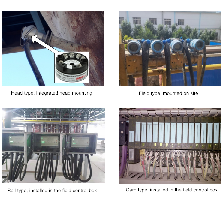
The structure and installation position of the temperature transmitter are divided into the following four situations:
lHead type, integrated head installation
l Field type, with housing, installed on site
l Guide rail type, installed in the on-site control box
l Card type, DCS/PLC/remote IO input module
The dimensions of the head-type temperature transmitter must be compatible with the connection box type B according to DIN EN 50446. If technically feasible and cost-effective, the outer diameter of the head-type temperature transmitter should not exceed 43mm. Fixing screws and terminal screws must be of non-volatile construction.

The temperature transmitter output signal must be within the claimed accuracy range, or must comply with a NAMUR fault/diagnostic signal. Signals with incorrect values are not allowed to be output at any time. Even if an error occurs during the measurement process, an output signal with an incorrect value will not be issued.
2. Microcyber’s Digital temperature transmitter
Head type: NCS-TT106H: HART protocol single-channel temperature transmitter NCS-TT106P: PROFIBUS PA protocol single-channel temperature transmitter NCS-TT106F: FF H1 protocol single-channel temperature transmitter | |
Rail type: NCS-TT106H-R1: HART protocol single-channel temperature transmitter NCS-TT106P-R1: PROFIBUS PA protocol single-channel temperature transmitter NCS-TT106F-R1: FF H1 protocol single-channel temperature transmitter | |
NCS-TT108P: PROFIBUS PA protocol multi-channel temperature transmitter NCS-TT106F-R1: FF H1 protocol multi-channel temperature transmitter | |
Field type: NCS-TT105P: PROFIBUS PA protocol dual-channel temperature transmitter NCS-TT105F: FF H1 protocol dual-channel temperature transmitter |
<< Previous page
Next page >>