Profound and Detailed
2024-10-22
"HART Physical Layer Test (1)" describes the first three items: HART waveform test, carrier start/stop and delay time test, and HART signal instantaneous start and stop test.
This article goes on to talk about the last six items: output sound test at rest, analog change rate test, input impedance test, transmit impedance test, noise margin test and carrier detection test.
Output noise test at rest
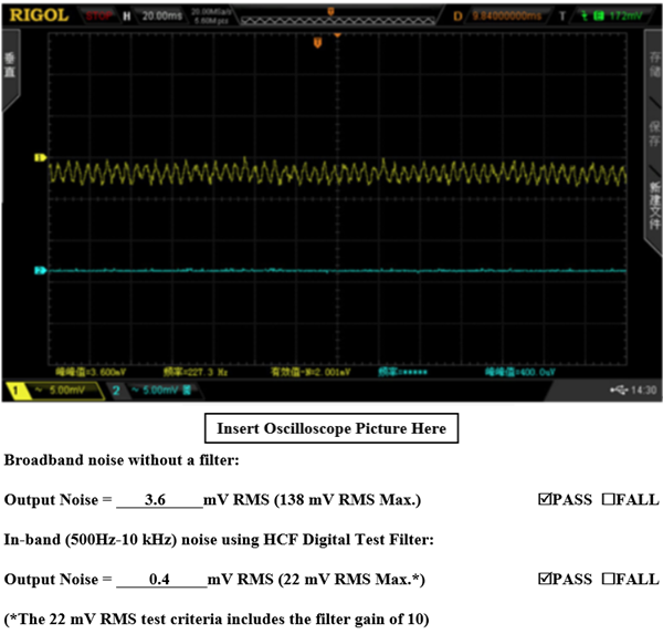
When a HART master or slave device is not transmitting a (quiescent) HART signal, no noise can couple into the HART passband. Excessive noise will affect the reception of HART signals. And although the noise from one device is very small, it will have a large additional impact on HART slave devices configured in multiple sites. The figure below shows the noise waveforms passing through the front and back ends of the analog filter.

Simulated rate of change testing
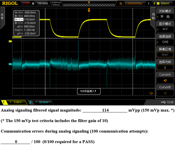
When the slave device changes the 4~20mA analog current, the maximum change rate of the analog current cannot affect the communication of the HART signal. This test requires the customer to pre-write a HART command for testing the simulated change rate. The figure below shows the noise waveforms passing through the front-end and back-end of the digital filter.

Input impedance test
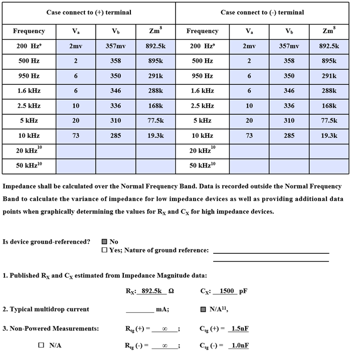
Input impedance can reflect the number of HART devices in a multi-site system and the maximum distance the HART signal can be transmitted. The input impedance value of the HART device at different frequencies can be calculated through the formula and example list in the figure below.
The calculation formula is:

The following are the test results of high-resistance equipment:

Send impedance test
The transmit impedance can also reflect the number of HART devices in a multi-site system and the maximum distance of HART signal transmission. This test item only tests low-resistance equipment, actuator equipment and auxiliary equipment. The formula and example list in the figure below can calculate the impedance value of the HART device at different frequencies. The sending impedance X0.8 is required to be less than the input positive impedance. The following are the calculation formulas and test results of low-resistance equipment:

Noise tolerance test
Noise tolerance testing means that under poor noise conditions, the HART device can still receive valid HART signals. Noise tolerance test requirements are shown in the table below:

Carrier Detect Test
The content of the carrier detection test means that the HART receiving device must be able to ignore signals below 80mVpp and must be able to accept signals above 120mVpp. The following table is a sample of the carrier detection test.

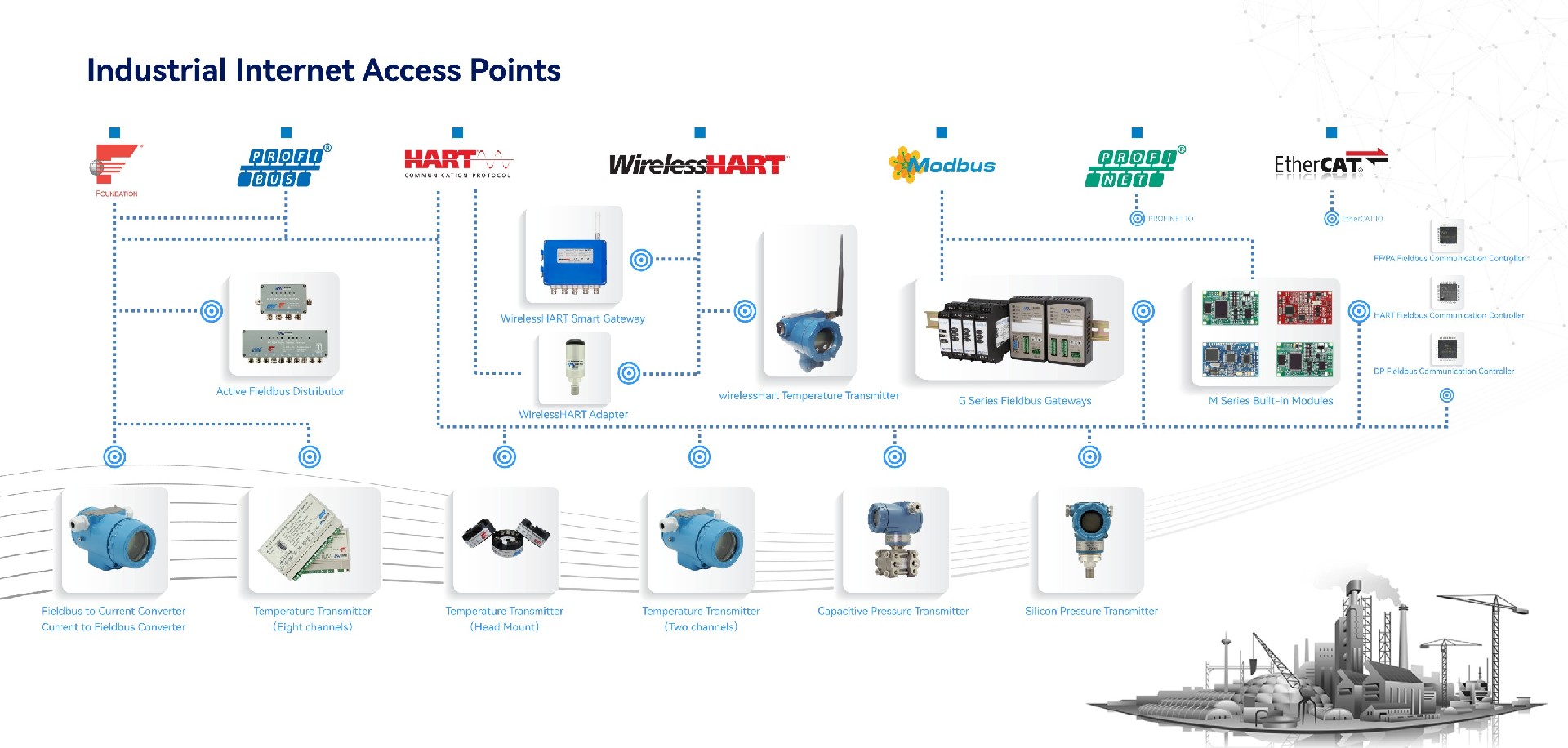
Industrial Internet Access Point
Microcyber is committed to the research and development, production, sales and integrated application of industrial IoT products.
Microcyber is the first fieldbus protocol stack in China and the third in the world to pass international certification, the first fieldbus instrument in China to pass international certification, the first demonstration application of networked control system in China, and the first function in China to pass international certification, the first wireless HART product in China to pass international certification, etc.
Microcyber is one of the main undertaking units of important national science and technology projects in the fields of industrial Internet of Things and industrial automation. Over the years, we had undertaken a number of major national science and technology projects, the National High Technology Research and Development Plan (863 Plan), and the development of intelligent manufacturing equipment. Special projects and other national science and technology plans.
Microcyber has accumulated rich experience in technical capabilities, technical achievements and technical reserves, and has a strong R&D team to protect the sustainable development of the company's products.

<< Previous page
Next page >>