Profound and Detailed
2024-09-24
Temperature transmitter is used to continuously measure resistance and millivolt voltage signals and convert them into temperature values. NCS-TT106H HART protocol temperature transmitter converts the temperature value into a 4~20mA analog current signal output that is superimposed on the HART digital signal. This specification applies to the NCS-TT106H head type and NCS-TT106H-R1 rail type HART protocol temperature transmitters (hereinafter referred to as "temperature transmitter"). The temperature transmitter has undergone board-level normal temperature calibration and inspection, complete machine high and low temperature calibration and inspection, and complete machine normal temperature inspection during the production process.
This specification is formulated based on China's National Metrology Technical Specification "JJF 1183 Temperature Transmitter Calibration Specification" - 2007. It stipulates the procedures and methods for calibration and inspection of temperature transmitters before leaving the factory, and provides users with instructions for regular calibration and inspection during use. suggestion. Each temperature transmitter must be factory calibrated and inspected in accordance with this specification before leaving the factory.
The periodic calibration and inspection cycle is five years, and the factory date of the temperature transmitter is the starting time of the periodic calibration and inspection cycle. It is recommended to users that temperature transmitters that do not exceed the periodic calibration and inspection period do not need to undergo periodic calibration and inspection. Temperature transmitters that are reactivated after exceeding the periodic calibration and inspection period or that are malfunctioning require additional calibration and inspection.
1. Calibration and inspection operations
Operation | Calibration and Inspection Types | Calibration and Inspection Types | ||
Serial No. | Name | Factory | Regular | |
1 | Appearance inspection | 4.1 | yes | yes |
2 | HART communication function check | 4.2 | yes | yes |
3 | Cold end temperature inspection | 4.3 | yes | yes |
4 | 4~20mA calibration/inspection | 4.4 | yes | yes |
5 | 12mA current value test | 4.5 | yes | yes |
6 | RTD calibration and inspection | 4.6 | yes | yes |
7 | TC calibration and inspection | 4.7 | yes | yes |
8 | Calibration and inspection reports | 5 | yes | yes |
If the result of any factory inspection operation is unqualified, the inspection will be stopped and the product will be returned for repair. After correcting the unqualified items, the factory inspection will be repeated.
In the regular calibration recommendations, if any items that do not affect the use are unqualified, the user can decide whether to give in to the use.
2. Calibration and inspection equipment
✧ Millivolt signal generator, recommended model: Fluke 5500A, or the same device with an accuracy not less than the recommended model;
✧ Digital multimeter, recommended model: Keithley2000, or the same instrument with an accuracy no less than the recommended model;
✧ Programmable resistance box, recommended model: MEATEST M632, or the same type of appliance with accuracy no less than the recommended model;
The above calibration and inspection instruments should be kept in good condition and have valid calibration certificates.
HART master device, which can be any of the following four types:
• HART handheld communicator that can import FDI packages (DD files);
• Import FDI package, third-party DCS/PLC main control system with HART master module;
• A personal computer plus a third-party configuration software with HART master function that can import FDI packages;
• Personal computer plus HartMPT.exe host computer configuration software provided by Microcyber;
3. Calibration and inspection conditions
✧ The ambient temperature is (20±2)℃;
✧ The relative humidity of the environment is between 45% and 75%;
✧ Except for the geomagnetic field around the temperature transmitter, there is no external magnetic field that affects the normal operation of the temperature transmitter;
✧ The power supply is DC 24V, and the voltage change rate does not exceed ±1% when the load is 0.5A;
✧ Leave the temperature transmitter powered on for at least 30 minutes;
✧ Keep the calibration and inspection equipment in the same environment for at least 1 hour, and power on for at least 5 minutes before starting the test;
4. Carry out calibration and inspection
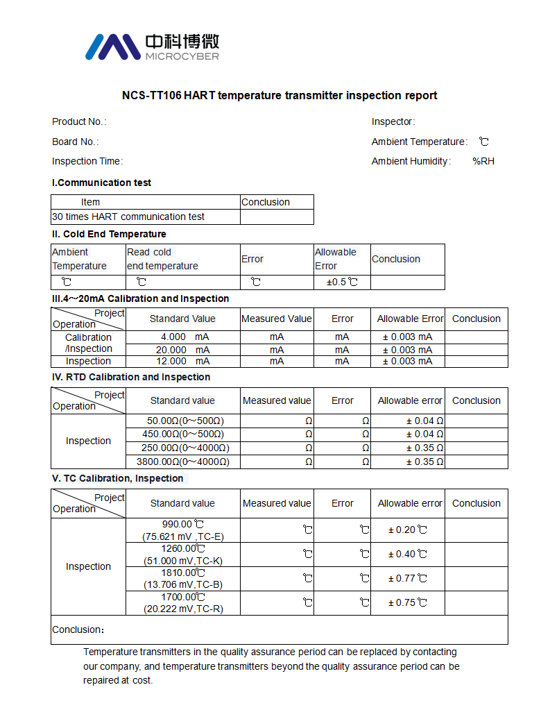
Keep data records during calibration and inspection to fill in the inspection report in Section 5.
4.1 Appearance inspection
✧ There are no obvious defects in appearance, and the wiring screws are not missing and are in a tightened state
✧ The supporting parts are consistent with the list listed in the certificate
✧ The markings on the nameplate are consistent with the certificate
If the supporting parts and product numbers are consistent with the certificate of conformity, the nameplate markings are consistent with the instructions for use, and there is no mechanical damage that affects normal use, the appearance inspection is deemed to have passed the inspection.
4.2 HART communication function inspection
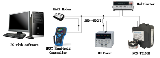
Connect the NCS-TT106H, DC power supply, and HART master device as shown below. Operate the HART master device to read the dynamic variables of NCS-TT106H and communicate continuously for 30 times. If the number of failures/errors is not 0, the communication function is judged to be unqualified.

The figure above shows the connection method between a personal computer running the configuration software or a handheld terminal and the NCS-TT106H. You can choose one of the two HART master station devices.
4.3 Cold end temperature inspection
As shown in the figure above, the NCS-TT106H temperature transmitter is connected to an external PT100 to measure the cold-junction temperature. The HART master station device is configured with a temperature transmitter connected to any type of sensor, and the cold-junction compensation method is external. Read the cold junction temperature of the temperature transmitter and compare it with the ambient temperature. If the difference between the cold end temperature and the ambient temperature is greater than ±0.5°C, the test is judged to be unqualified.
4.4 4~20mA calibration/inspection
Connect the NCS-TT106H, DC power supply, HART master station device, and digital multimeter as shown below to calibrate the NCS-TT106H analog current output circuit.

Send HART commands to calibrate 4.000mA and 20.000mA respectively through the HART master device. After stabilizing for at least 5 seconds, read the reading of the digital multimeter (for example: Keithley2000) as the measured value, and manually enter the measured value into the HART master device, and Click OK. NCS-TT106H compares the output current value with the measured value, and corrects the output current value. The measurement value can be input multiple times until the error of the output current value at two points is not greater than ±0.003 mA. The calibration of the two-point currents of 4mA and 20mA will affect each other and may require repeated calibration. However, if it is still unqualified after more than 3 cycles, it can be determined that the 4~20mA output circuit is faulty, and the calibration/inspection result is unqualified.
4.5 12mA current value inspection
Connect the NCS-TT106H, DC power supply, HART master station equipment, and digital multimeter as shown above for 12mA current value inspection.
Send a fixed current output command with a current value of 12.000mA through the HART master device and stabilize it for at least 5 seconds. Read the reading of the digital multimeter as the measurement value. If the error is greater than ±0.003 mA, the inspection result is unqualified.
4.6 RTD calibration and inspection
Connect the resistance box to NCS-TT106H according to the 4-wire system as shown in the figure below, and control the resistance box to give the calibration point resistance. Each time the resistance value of the resistance box is changed, it should be stable for at least 5 seconds (the same below). Then issue the "RTD calibration" special command through the HART master device.
The calibration points are "0Ω", "400Ω" and "3200Ω". The calibration process should be carried out according to the "0Ω", "RTD calibration" command, "400Ω", "RTD calibration" command, "3200Ω", "RTD calibration" ” command sequence to complete RTD calibration in one go.

After completing the RTD calibration, send the sensor type configuration command through the HART master device to configure the sensor type of NCS-TT106H to 4-wire 0~500Ω. The control resistance box gives "50Ω" and "450Ω" resistance respectively. The resistance value is read by refreshing the dynamic variable on the HART master station device. If the error is greater than ±0.04Ω, it is judged as unqualified.
Then, configure the sensor type of NCS-TT106H to 4-wire 0~4000Ω. The control resistance box gives "250Ω" and "3800Ω" resistance respectively. The resistance value is read on the HART master station device by refreshing the dynamic variable. If the error is greater than ±0.35Ω, it is judged as unqualified.
4.7 TC calibration and inspection
Connect the output signal of the millivolt signal generator or thermal calibrator to the NCS-TT106H as shown below, and control the millivolt signal generator to give a "+50mV" millivolt signal. Each time the output signal of the millivolt signal generator is changed, it should be stable for at least 5 seconds (the same below). Then issue the "TC calibration" special command through the HART master station to complete the TC calibration.

After completing the TC calibration, send the sensor type configuration command through the HART master station device to configure the NCS-TT106H as "TC-E", "TC-K", "TC-B", and "TC-R" thermocouples. , turn off the cold junction compensation function. Control the millivolt signal generator to output a millivolt signal corresponding to the temperature value of the inspection point. This signal is the millivolt voltage value when the cold junction temperature is 0°C (see GB/T 16839.1 - 2018 Thermocouple Part 1: Electromotive Force Specifications and Allowances difference, or IEC 60584-1:2013).
On the HART master device, read the temperature value by refreshing the dynamic variable.
TC-E type thermocouple, the inspection point is 990.0℃ (75.621mV), if the error is greater than ±0.2℃, it is judged as unqualified.
TC-K type thermocouple, the inspection point is 1260.0℃ (51.000mV), if the error is greater than ±0.4℃, it is judged as unqualified.
TC-B type thermocouple, the inspection point is 1810.0℃ (13.706mV), if the error is greater than ±0.77℃, it is judged as unqualified.
TC-R type thermocouple, the inspection point is 1700.0℃ (20.222mV), if the error is greater than ±0.75℃, it is judged as unqualified.
5. Inspection results report

<< Previous page
Next page >>