
Profound and Detailed
Three Realization Methods of Domestic Chip HT1200M Clock
2024-04-29
As we all know that HART communication chip A5191HRT needs 460.8KHz passive crystal to run, as the perfect compatible chip of A5191HRT, HT1200M also needs 460.8KHz passive crystal for the chip to use. HT1200M chip development using the clock usually have three methods, respectively, the use of external 460.8KHz passive crystal, the use of microcontroller MCO pin (MCO on behalf of the Microcontroller Clock Output, which is a microcontroller clock output pin), the use of microcontroller timer PWM output method. The following is a brief description of each.
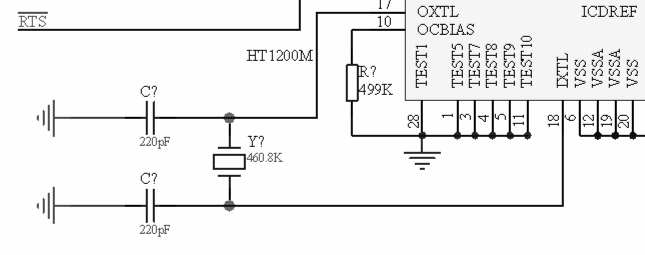
Way 1: Use external 460.8KHz passive crystal oscillator
HT1200M clock input pin connection 460.8KHz, this method of use is also the most used over the years, the following figure is the HT1200M and passive crystal connection schematic.
Way 2: Output using the MCO of the microcontroller
The example of using a 3.6868MHz passive crystal for the microcontroller STM32L010RBT6 is illustrated.
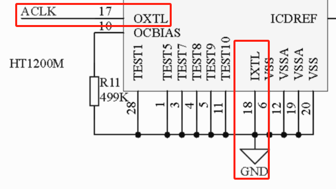
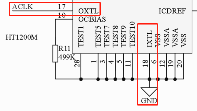
● The HT1200M chip's pin 17 "OXTL" is connected to the microcontroller's MCO output pin (i.e., labeled ACLK), and pin 18 "IXTL" is connected to the microcontroller's "GND ".
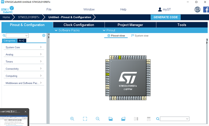
●Open the STM32CubeMX executable program, select the STM32L010RBT6 microcontroller, and enter the following interface.
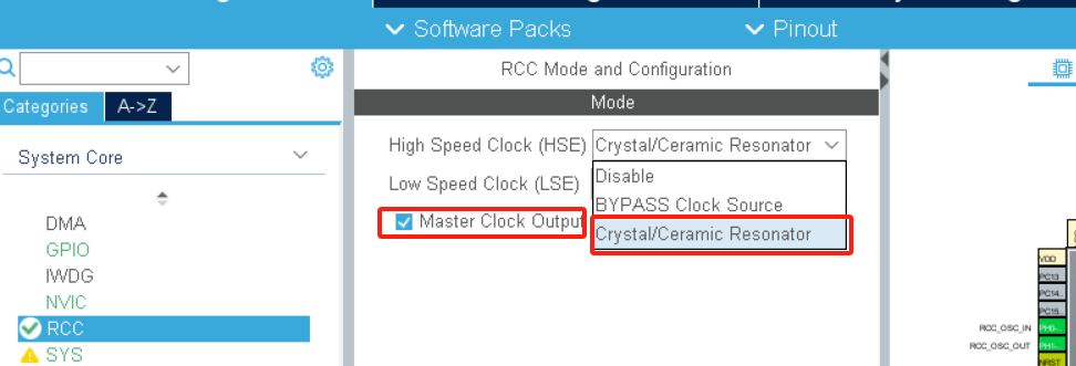
● Enter the System Core menu item and click RCC to enter the RCC Mode and Configuration interface, select Crystal/Ceramic Resonator in the Hight Speed Clock (HSE) drop-down menu, and check Master Clock Output 1.
● Click Clock Configuration interface, input 3.6864MHz in input frequency box; select HSE for System Clock Mux.

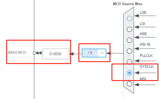
● System Clock Mux selects HSE; MCO Source Mux selects SYSCLK, and the crossover frequency box selects "/8", which can get the crossover frequency of 0.4608MHz and output it to the pin of MCO.
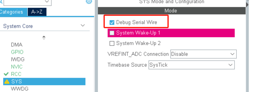
● Go to System Core menu item and click SYS, enter SYS Mode and Congfiguration interface, check Debug Serial Wire.
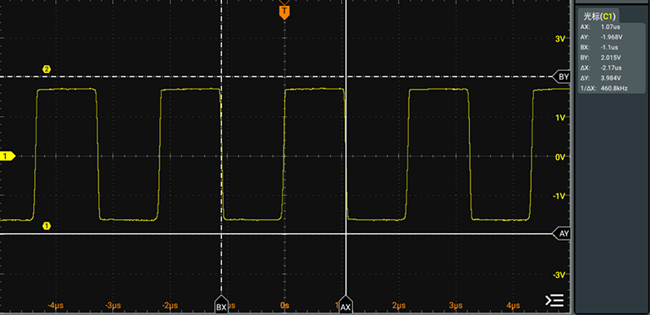
● After the configuration is completed, generate the code and run it, and capture the pin signal of MCU MCO through the oscilloscope to get the waveform (460.8KHz) as follows.
Way 3: Using the timer PWM output mode of the microcontroller
Timer output mode to the microcontroller STM32L010RBT6 using 3.6868MHz passive crystal as, signal output pin PA0 as an example to illustrate.
● The HT1200M chip's pin 17 "OXTL" is connected to the microcontroller's PA0 pin (i.e., labeled ACLK), and pin 18 "IXTL" is connected to the microcontroller's "GND ".
● Open the STM32CubeMX executable program, select the STM32L010RBT6 microcontroller, and enter the following interface.
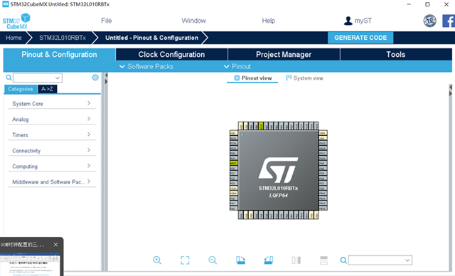
● Open STM32CubeMX executable program, select STM32L010RBT6 microcontroller, and then enter the following interface.

● Click Clock Configuration interface, input frequency box: 3.6864MHz; System Clock Mux select HSE.

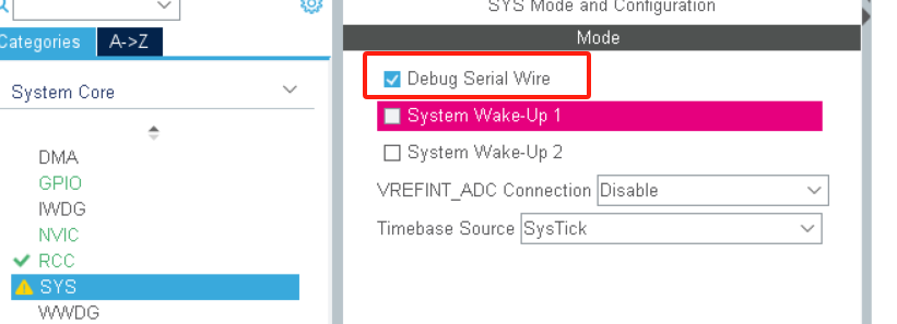
● Enter System Core menu item and click SYS, enter SYS Mode and Congfiguration interface, select Debug Serial Wire.
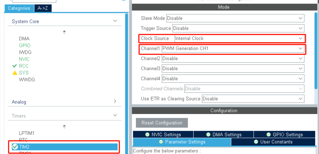
● Select TIM2 in Timers, select Internal Clock for Clock Source; select PWM Generation CH1 for channel1.

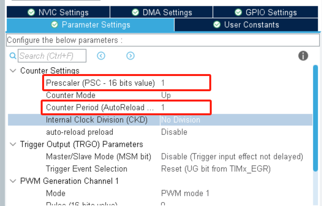
● Under Configuration->Parameter Settings->Counter Settings in TIM2 menu, set the variables Prescaler (PSC-16 bits value: 1; Counter Period (AutoReload Register-16 bits value): 1; Counter Period (AutoReload Register-16 bits value): 1; Counter Period (AutoReload Register-16 bits value): 1; Counter Period (AutoReload Register-16 bits value): 1. value): 1
● After the configuration is completed, generate the code, in the main( ) program, add the capture/comparison register (CCR) related code.
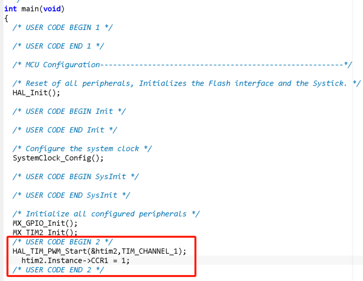
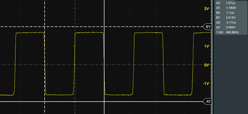
● Run the code in the microcontroller's PA0 pin output signal through the oscilloscope to capture the following waveform graph (460.8KHz)
The above three clock output methods, external passive crystal and MCO output methods are the most commonly used, and the timer method is the most flexible, I hope to give you some help in the development process of HART communication.
Microcyber is committed to the research and development, production, sales and integrated application of industrial IOT products.
It has the first domestic and the third internationally certified fieldbus protocol stack, the first internationally certified fieldbus instrument in China, the first networked control system demonstration application in China, the first internationally certified functional safety instrument in China, the first internationally certified wireless HART product in China and so on.
Microcyber is one of the main bearers of national important science and technology plan projects in the field of industrial IOT and industrial automation, and has undertaken many national science and technology major projects, national high technology research and development program (863 program), intelligent manufacturing equipment development special projects, and other national science and technology plan projects over the years.
The company has accumulated a wealth of experience in technical capabilities, technical achievements and technical reserves, and has a group of strong R & D team for the continuous development of the company's products.
<< Previous page
Next page >>