
Profound and Detailed
2023-06-29
People who use thermocouples a lot may also not be that aware of how the cold end (reference) of a thermocouple actually works. In order to discuss the cold end, we first need to have a brief understanding of thermocouple theory and how thermocouples work.
● Cold End or Reference End
The "cold end" of a thermocouple is often referred to as the "reference end", but it seems that the term "cold end" is more often used.
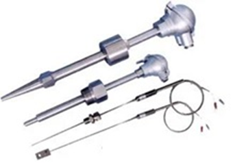
Common thermocouple
Thermocouples are prevalent in industrial temperature sensing applications because they can measure temperatures that are too high for resistive temperature sensors (RTDs). They are also more robust than RTDs, making them less prone to damage. Although thermocouples may not be as precise as RTDs, their level of accuracy is sufficient in many applications.
● How Thermocouples Work
A thermocouple typically comprises two electrical conductors made of different materials that are connected at one end (the "hot" end), where temperature is measured. When the junctions of these two conductors are subjected to different temperatures, a thermal current is generated, producing a small voltage between the open ends of the wires. This phenomenon is referred to as the "Seebeck effect," discovered by Thomas Johann Seebeck in 1821.
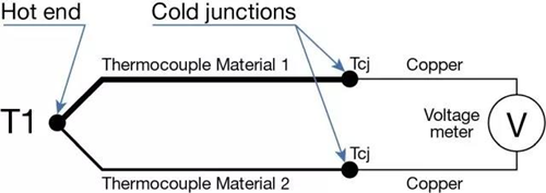
Simplified schematic diagram of thermocouple
In the diagram above, "thermocouple materials 1 and 2" represent the two distinct materials used in thermocouples. The "T1" denotes the hot end of the thermocouple where temperature measurement occurs. The two "TCJs" are the cold ends of the thermocouple. A thermal voltage is generated between the "hot" and "cold" ends due to the temperature gradient in the thermocouple wire. Although technically, the thermal voltage arises from the temperature gradient along the wire, the explanation that it is generated between the hot and cold ends is commonly used.
● Thermocouple Types and Materials
Thermocouples come in various types and alloys with different sensitivities and thermal voltages at the same temperature. The materials used in creating thermocouples are unique, and these materials affect their characteristics. Some of the standardized thermocouple types are designated by one-letter labels such as types K, R, S, J, K, etc.
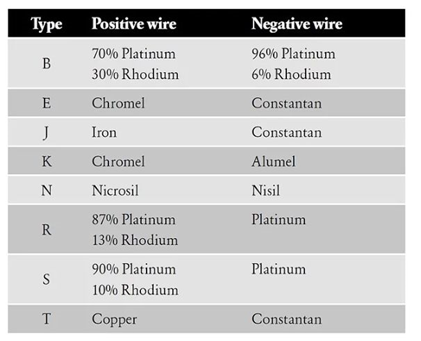
common thermocouples and their materials
Since different thermocouples are made of different materials, the thermoelectric voltages are also different, as shown in the figure below.
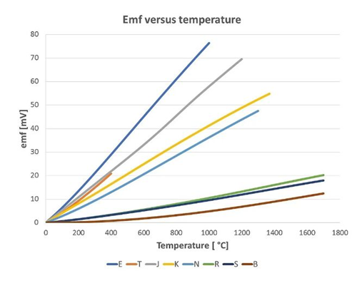
thermal voltage of a thermocouple
● Cybek coefficient of thermocouples
If you want to measure lower temperatures, it is obviously best to use more sensitive types as they offer higher voltages and are easier to measure. However, if you need to go to high temperatures, you may want to choose some of the less sensitive types that can be used at extremely high temperatures. The Seebeck coefficient indicates how much the thermocouple voltage changes relative to the temperature. The chart above illustrates the different sensitivities between different thermocouples and explains why thermocouple calibrators typically have different accuracy levels for different types of thermocouples.
● Cold End
The simplified thermocouple schematic above portrays two different conductors joined to create a thermal voltage at the "hot end." However, one may wonder, "What about the other end of the wire?" When the voltage of a thermocouple is measured, the thermocouple wire is connected to a voltmeter. The voltmeter usually uses copper or copper-plated material in its connections, which is different from the thermocouple's material, creating two additional thermocouples at the voltmeter connections!
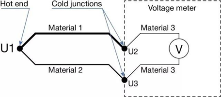
In the diagram above, material 1 and material 2 collectively form the thermocouple. The hot end is the point where they are joined, where temperature measurement is taken and voltage U1 is generated. The voltage U1 is what we want to measure. At the "cold end," the thermocouple connects to a voltmeter with a connection made from a different material (material 3). As long as the different materials are in the same ambient temperature, they generate additional voltages U2 and U3 that have no effect on the total thermal voltage. The thermal voltage value in the reference table indicates the sum of voltages generated by the thermal gradient from the hot end to the cold end when the cold end is at 0 ℃. In practice, the ambient temperature at the cold end of the temperature transmitter and thermocouple is usually not at 0℃in most cases; hence, the effect produced by the temperature at the cold end must be eliminated when using the reference table to calculate the temperature at the hot end. This process is referred to as cold end compensation.
● Selection and Compensation Method for the Cold End
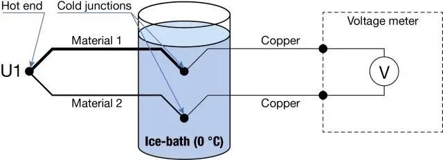
1. Freezing Point Slot Method
Due to the inherent nature of thermocouple joints, they do not generate any thermal voltage at a temperature of 0°C (32°F). Therefore, the cold end can be connected at this temperature, such as in a freezing bath or a precision temperature calibration oven. The thermocouple wire can be connected to the copper wire in the freezing bath without any thermal voltage being generated during the connection. However, to avoid any leakage currents that may cause errors or corrosion, the connection must be electrically isolated from the water in the ice bath. This precise method is often used in calibration labs, but is less practical in factories.
2. Cold End at Fixed Temperature
As ice baths are not practical, cold end connections can be made at a known fixed temperature using a small junction box with a temperature control device. Normally, the temperature is higher than the ambient temperature, so the box only needs to be heated, not cooled.

When the temperature of the cold end and the type of thermocouple are known, the thermal voltage of the cold end can be calculated and compensated. Many measuring devices or temperature calibrators have the ability to enter the temperature of the cold end and compensate automatically.
3. Automatic Compensation of Cold End Temperature During Measurement
Allow the measuring device to calculate the compensation automatically. The measuring device (transmitter, DCS input card) can measure the cold end temperature at any time and automatically compensate for any cold end errors online. As the measuring device also knows the type of thermocouple, it can compensate automatically and continuously.

This is necessarily the easiest and most practical way to compensate for cold junctions in normal measurements and calibrations, since you don't need to worry about the cold junction, but let the equipment handle it.
● Cold End Compensation of NCS-TT106
The modular temperature transmitter products of Microcyber are available in HART, PROFIBUS PA, and FF H1 protocols.
The NCS-TT106 supports all the above cold end compensation methods, of which there are two methods for automatic compensation of measuring cold end temperature. You can choose to use the built-in temperature sensor close to the terminal or an external platinum resistance temperature sensor. The temperature measurement accuracy of the built-in temperature sensor is ±0.5℃, and the temperature measurement accuracy of the external PT100 platinum resistance temperature sensor is ±0.15℃.
<< Previous page
Next page >>