
Profound and Detailed
2024-03-18
1. Thermoresistance measurement
●Thermoresistance input signal processing
Thermoresistance sensors are usually connected using a four-wire configuration, which consists of two wires for supplying driving current to the thermoresistance sensor and two wires for measuring the voltage across the thermoresistance sensor. This connection method provides the widest diagnostic coverage for temperature sensors (including the wires) through the temperature transmitter.
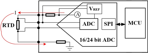
Four-wire thermoresistance driving and measurement
The three-wire connection method is commonly used in the industry. However, measurement errors that cannot be eliminated may occur when the lengths and materials of the three wires are different.
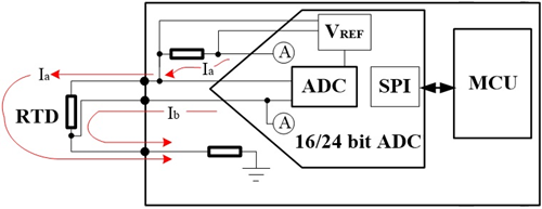
Three-wire RTD driving and measurement
When using two-wire connection, the resistance of the wires completely enters the overall measurement error. The temperature transmitter can eliminate the wire resistance by zeroing the two-wire connection resistance.
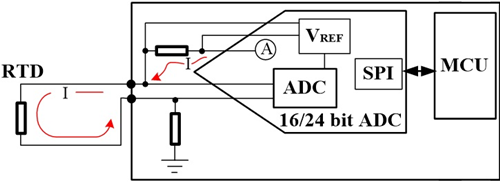
Two-wire RTD driving and measurement
●Sensor Driving Current
If the driving current of the sensor is too low, there is a risk of severe influence from the thermoelectric voltage at the terminal on the measurement signal, and the minimum value must ensure that the thermoelectric voltage at the terminal can be ignored. If the driving current of the sensor is too high, the RTD sensor will be heated. Therefore, the sensor driving current should not exceed 1mA.
● Sensor circuit resistance
For head-mounted temperature transmitters, the sensor circuit resistance should be at least 20Ω. For rail-mounted and field-mounted temperature transmitters, the sensor circuit resistance should be at least 50Ω. If the circuit resistance exceeds this value, the output signal can be switched to an error mode that complies with NAMUR recommendations.
● Open circuit, circuit/sensor break
Open circuit or break not only refers to a physical break in the circuit or sensor, but also to the situation where the sensor resistance exceeds the highest temperature defined in the DIN EN 60751 standard for thermoresistors. The temperature transmitter must reliably detect circuit/sensor breaks and switch the output signal to an error mode that complies with NAMUR recommendations.
● Circuit/Sensor Short Circuit
Short circuit not only means a physical short circuit in the circuit or sensor, but also means that the sensor resistance is less than the minimum temperature defined in the DIN EN 60751 standard for thermoresistors. The temperature transmitter must reliably detect the circuit/sensor short circuit and switch the output signal to the error mode recommended by NAMUR.
2. Thermocouple Measurement
● Thermocouple Input Signal Processing
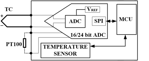
For thermocouples using the temperature transmitter's internal reference terminal, they should be connected to the temperature transmitter using extension compensating cables or compensating cables. For those using the temperature transmitter's external reference terminal, copper wires can be used to connect to the temperature transmitter.
●Open circuit, circuit/sensor break
An open or broken circuit means not only a physical break in the line or sensor, but also a sensor line voltage higher than the maximum temperature of the thermocouple as defined by the DIN EN 60584-1 standard. The temperature transmitter must reliably detect open circuits, line/sensor breaks and switch the output signal to an error mode in accordance with NAMUR recommendations.
● Line resistance
The allowable line resistance is a combination of sensor wire and thermocouple. Head-type temperature transmitters should have a minimum of 5 kΩ. rail-type, field-type temperature transmitters should have a minimum of 10 kΩ. above the line resistance, the output signal can be switched to an error mode that complies with NAMUR recommendations.
● Sensor short circuit
Detection of sensor shorts is considered very difficult, but it is desirable. It is common to equate the shorted position of the upstream thermocouple to a parallel circuit, which produces measurement errors.
3. Microcyber's temperature transmitters
Mode | Channel | RTD Wire System | ||
Head type | NCS-TT106H | 4~20mA+HART | 1 | 2、3、4 |
NCS-TT106P | PROFIBUS PA | 1 | 2、3、4 | |
NCS-TT106F | FF H1 | 1 | 2、3、4 | |
Rail type | NCS-TT106H-R | 4~20mA+HART | 2 | Channel 1:2、3、4;Channel 2:2、3 |
NCS-TT106H-R1 | 4~20mA+HART | 1 | 2、3、4 | |
NCS-TT106P-R1 | PROFIBUS PA | 1 | 2、3、4 | |
NCS-TT106F-R1 | FF H1 | 1 | 2、3、4 | |
NCS-TT108P | PROFIBUS PA | 8 | 2、3 | |
NCS-TT108F | FF H1 | 8 | 2、3 | |
On-site type | NCS-TT105P | PROFIBUS PA | 2 | Channel 1:2、3、4 ;Channel 2:2、3 |
NCS-TT105F | FF H1 | 2 | Channel 1:2、3、4 ;Channel 2:2、3 |
The NCS-TT108 can be mounted either on a rail or on a tray. The head type NCS-TT106x can also be mounted on a rail with additional mounting accessories.
NCS-TT106x | NCS-TT106x-R1 |
The RTD drive current of Microcyber’s temperature transmitter is between 0.21mA and 0.84mA depending on the wire system and sensor type. When used for RTD measurement, the maximum resistance of single cable of sensor lead is 50 Ω. When used for thermocouple measurement, the maximum total resistance of sensor cable is 10 kΩ.
NCS-TT105x dual channel temperature transmitter |
NCS-TT108x multi-channel temperature transmitter |
4. Recommendation NE 43 Standardisation of Fault Message Signal Levels for Digital Transmitters.
Mode | Current Type | Configurable range(mA) | Factory default(mA) |
NCS-TT106H | Saturation Current | 3.75 ~ 4.0 ;20 ~ 20.8 | 3.8 ;20.5 |
Alarm Current | 3.5 ~ 3.7 ;21 ~ 22.5 | 3.6 ;21.75;High alarms | |
NCS-TT106H-R | Saturation Current | 3.75 ~ 4.0 ; 20~20.8 | 3.8 ;20.5 |
Alarm Current | 3.5 ~ 3.7 ;21 ~ 22.5 | 3.6 ;21.75;High alarms | |
NCS-TT106H-R1 | Saturation Current | 3.75 ~ 4.0 ;20 ~ 20.8 | 3.8 ;20.5 |
Alarm Current | 3.5 ~ 3.7 ;21 ~ 22.5 | 3.6 ;21.75;High alarms |
The temperature transmitters of Microcyber are all in line with the above mentioned short-circuit and disconnection handling in RTD and HART measurement. Among them, the output current of 4~20mA+HART protocol temperature transmitter is shown in the above table, which is in accordance with NE 43 recommendation.
<< Previous page
Next page >>